
Producing fiNe-scale wheels
Updated method

Set of wheels and tools for a series of Br52 wheels, new tyres are turned from automate steel and polished using a wet and dry stick of 800 paper.
Over the years methods change. Current preference for production is the method by mounting new tyres, instead of mounting a new flange only. The tyres are generally turned from automate steel, these simply look better than wheels from Nickel Silver, apart from automate steel being much easier to obtain in diameters and lengths for home use. For 'large' amounts of wheels of identical size producing some additional tools is helpful. For producing tyres I currently use a Proxxon lathe ( model 230 out of production), which is equiped with quick change toolposts, a set of 4 is minimum in my view. This allows fast changing between different cutters without having to re-set the height of your cutter after change.
Further producing a dedicated collet allows better grip on your wheel. The main problem with commercial collet holders is that the wheel lies too deep and you need cutters with a deep cutout or nose to keep free of the edge of the collet holder. The photo above shows such a dedicated collet made from brass for wheels of the Br 52. This collet is mounted in the ordinary 3 claw chuck. In this collet the wheel stands several mm free from the chuck and can be worked upon with usual cutting tools. The 3 grooves are hand cut with a jewellers saw mounted with a relative thick blade. The rim takes care that it is always mounted to the same depth. The depth for the tyre is 1.0 mm as precisely made as possible. On the inner end beyond the grooves the diameter is slightly reduced, thus the claws only grip on the part with grooves allowing to close it. This collet also allows finishing the back of the new tyre to exact thickness, chamfering of the back of the flange and rounding of the outer edge of the rim, followed by a final polishing with a wet and dry stick. This produces wheels that are well beyond those of the 2 mm SA standard with much better way finding properties.
The steel bit on the left is used for gluing/pressing the rims. The center has a well such that the higher surface parts of center, pinhole and weight are free. Thus wheel and rim are carried on the outer edge only. This allows the flange to be aligned to the front of the metal part of the wheel. You can thus use a press fit between tyre and wheel center apart from that any glue is only there for security. The wheel parts are dropped in the steel bit and the new tyre is pressed over the wheel center with the collet.
Instead of using the collet and the lathe for removing the part of the wheel that is still sticking out at the back of the rim, it is safer to use 2 minidrills and grind it off. One minidrill is mounted with an 1.5 mm axle with the wheel, the other with a blue grinding rubber. This allows removing metal and plastic without strain on the wheel center. This procedure lowers the risk that the wheel falls apart by strain caused by the cutter in the last process step.
The same tools can be used to mount such tyres on CNC-milled wheel centers or those from the 3D printer.
see skinnywheels
 Bringing the inner diameter to correct dimension with a small inner cutter.
 Cutting the tyre and flange with a dedicated cutter using the cross slide set at 2.5 degrees taper.
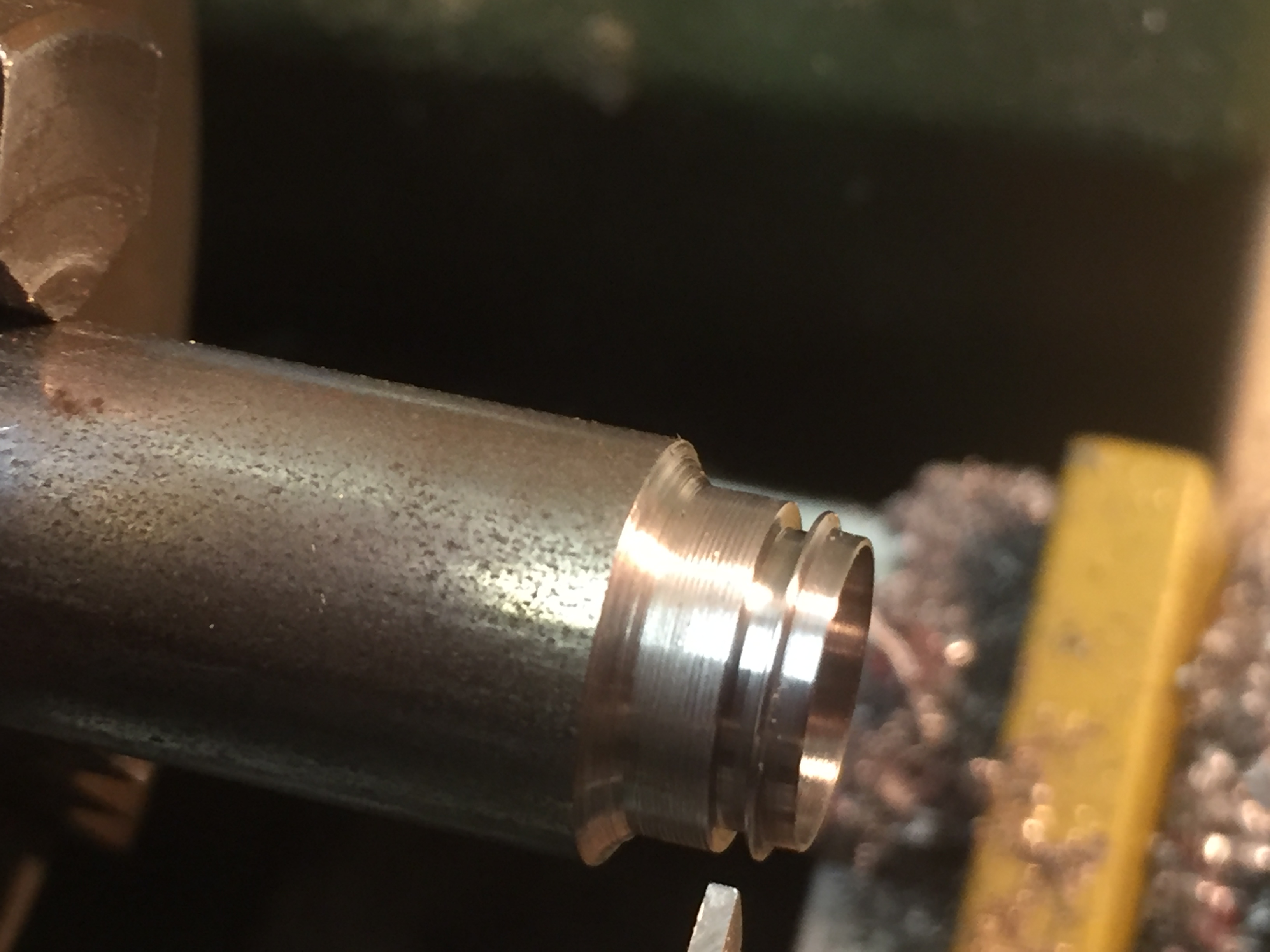 The tyre with flange just before parting off. In this stage you can measure flange thickness and correct this when too large. You can also add a bit of skew on the inside of the flange and then round the top edge of the flange using #4 file before cutting off. However using the collet you can finish the back of the wheel also in a later phase.
 When you mount an appropiate piece of steel in the drill chuck on cut-off then you don't have to search for the tyre in the garbage below!
 A photo of mounting the tyres, the brass core can be seen and will be removed after fitting the tyre.
This happen to be the wheels of a Minitrix BR44, an original riffled axle can be seen right hand top. These need to be replaced by new axles with a shorter body and without riffles as these are a nuisance on quartering.
A photo of mounting the tyres, the brass core can be seen and will be removed after fitting the tyre.
This happen to be the wheels of a Minitrix BR44, an original riffled axle can be seen right hand top. These need to be replaced by new axles with a shorter body and without riffles as these are a nuisance on quartering.
 This shows the parting-off of the old brass rim on the lathe to leave only the plastic. The wheel center is pressed home using a piece of redundant delrin and the rotating center to ensure that the wheel stays where it is.
The plastic can be cut off various ways: jewellers saw, scalpel, using a fine cutter or by grinding. The main items are not exert force on the plastic and prevent any burrs forming developing. Grinding is in this the best method but not the fastest. Instead of using the lathe you can grind the brass part and plastic away in a single operation.
You can finish the back of the wheel after parting off the plastic. If the flange was still too wide then this is your last chance to correct that and reduce it with the parting tool and finish with #4 file followed by a stick with wet and dry for final polishing.
 Mounting the wheels on the axle using the collet and a dedicated piece of steel with a well of the correct diameter mounted in the drill chuck. The piece of aluminium is acting as gauge to set the wheels to correct b-t-b distance. This is how the new drop-in axles for the Br44 look. This particular axle was the first one and disregarded for being too short, but it was still useful for staging up this photo. The red plastic centers still have the original width of the wheels, keeping this axle center as long as possible helps by preventing wheel wobble and make for a stronger wheel.
Old method
This page shows a quick way to produce fiNe-scale wheels from Fleischmann half-products.
The way that is shown here is not the only one, but I think it is one of the fastest and has a low risk on loss of wheels. The principle is to remove the original flange of the wheel and replace it with a new flange and then cut-off everything at the back that is superfluous. One alternative is to turn the whole tyre until a flat face exists and then put on a 1.3 mm width tyre. In this way you can change (reduce) the diameter of the wheel a little. The drawback of that method is that you need a higher reproducable accuracy as all the driving wheels need to have equal diameter. In the method shown here the original relation between axle and tyre keeps intact. If your wheel is uncircular it will not be better afterwards. The flange thickness is less critical as long as it is in the order of 0.3 mm thickness. Any height difference will not influence the running properties. And for wobble there is a rather large tolerance of .1 mm in pointwork although it won't be nice to see your loco running with that. For turning I use a Unimat lathe, the good old type 3 which is now over 22 years age but still OK.
The first step in the process is to turn a set of rings, which will form the new flanges.

This photo shows the machine, note that I use a higher quality 3-claw than
originally supplied.
The wheels used for this session are 8.45 mm diameter with 16 spokes. The usual
type for replacements on Prussian loco's. In this case the
flanges are turned from 10 mm Nickel-Silver rod but you can use
brass too. If you prefer to use brass it is possible to correct
the look by electroplating a layer of Nickel on top afterwards.
The outside is turned to a diameter of about 9.6 mm, not critical. The rod is
then bored with a 8 mm hole. Use a 8.0 milling cutter as last
stage. The photo shows the cutting of a flange using a 0.5 mm
cutting steel at a width of the new flange of approximately
0.4 mm. This cutter is made from 3 mm square Cobalt steel. The
0.5 mm width gives less loss of otherwise useful material, but a
wider cutter can be used as well of course.
In order to minimise the burrs on the inside of
the new flange I put in a close fitting piece of waste steel just
before the final cut through. This also takes care that you don't
have to search for your flange in the junk below.
What you can not see on this photo is that the
flange has a (~ 15 degrees) angle on the outside. This is simply
a quick haul with a file done when starting out.
Always produce at least the amount of flanges you need plus some surplus for
dropping on the workshop floor.

This is the next stage. What you see is a piece of white Delrin in the 3-claw. This has a recess for the extending coupling rod pinhole. The wheel is carried at the outer edge. The inner is drilled with a hole of 1.45 mm. The trick is that the piece of Delrin easily takes the 1.5 mm axle and clamps it with enough force for turning while you can still take the axle out and put it back again over and over. The drill head shows a 1.5 mm axle (from a 2 mm SA wheelset)

This photo shows how to mount a wheel. The axle is pressed in using the tailstock. The wheel rests on the flat face so the axle goes in perpendicular, minimising the chance on wheel wobble. When the axle is pressed home the drill head is loosened. The wheel is not in anyway fixed other than by its own grip. You could pin it by using a pin through the coupling rod pinhole. In practice this is not necessary as you have to treat it gentle anyway. If not, you will not be left with a wheel, it will simply fall apart during the process or develop a tremendous wobble due to excessive forces on the plastic part.

Not entirely sharp, but you get the idea.

This is the next step, turn off material until you arrive at diameter just larger than your flanges. The dark face is 1mm width and will form the new tyre. The distance to turn off can be measured from the back of the wheel using the indicator wheel on the lathe and the known overwidth dimension.

Now we can press on one of our new flanges. This is facilitated if you taper the outer edge of the wheel a bit. This can be done with a file, we will cut it off anyway later. We now have to stick the new flange to the wheel. This can be done with cyanoacrylate glue or with solder. I prefer low melt solder of 70 degrees (for white metal). For this I take the whole lot out of the 3 claw and put it back later in the same position. But if you don't trust this because your 3 claw has its own merites than you better use the glue method.

Here we see it after soldering, you also see the mark to replace the rod in the same position.
We can now form the back of the wheel.

Two views of the wheel. We first cut off the old metal of the rim. We can also see how much taper the plastic part has. Meaning that it will easily fall apart as there is nothing to hold it inside any longer other than a tiny rim at the front.

This is how to cut off the plastic without any stress on the wheel. Note put in the sawblade with the teeth wrong way pointing against the rotation of your lathe. This is a 40 teeth/cm sawblade, the finest you can buy. A scalpel can be used too depending on the plastic type used for the wheel.

Here we see the new flange brought to width with a fine rounded tool. Finishing can be with a fine swiss file #4 and some polishing with glasfiber brush.

Be sure to take out your wheel using the headstock like this. Take it from the drillhead and now gently push the wheel from the axle.

Now for total security use this type of glue to keep the plastic and the metal together. This is very very thin and hardens if no air is available, thus on the interface between plastic and metal. This is age old stuff, nowadays probably has a new package.
copyright: Henk Oversloot
date: 5 March 2002
updated: 16 June 2019
