
Dedicated wheels for your model
This page shows how to draw a wheel using Viacad to arrive at a wheel that resembles your model as close as possible instead of doing with generic products that happen to be available. The end result can be produced by CNC milling, 3D printing or laser cutting.
Introduction
The purpose of this action was to see if I can produce more skinny wheels for a type 25 because the available FLM models have wheels that are on the small side but have a relative thick wheel edge compared to the real thing. They probably have only a limited number of sizes of rims and in this case used the available size identical to those on the Prussian machines with 8.4 mm instead of 8.75 mm of the original. However in real life we can find machines that have remarkable skinny tyres as illustrated with the photo below.

An example of a machine with relative thin wheel tyres
I am working on a Mac thus the choice in drawing packages with a reasonable price tag is more limited than a on pc. But the big pro is of course that operating system and the inbuilt toolset, particularly that for handling all kind of graphics, is far better than on a pc. Viacad was selected after experiencing poor performance with TurboCad which turns out to be a rather bad clone of Viacad missing several useful options. I use the pro version and that package works reliably and performs stable but as with all packages it needs some learning time to build up experience.
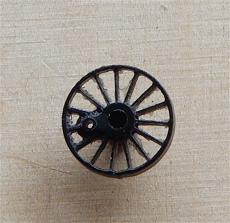
 A photo with a new spare wheel taken at some preservation railway.
Getting on with the work
First find some helpful photo reference of the thing we want to draw. Of course a drawing can be used too but as the final result needs to be a wheel to fiNe-scale standards its original dimensions needs to be adapted anyway. The cylinder stroke giving the offset for the pin for the rods can be taken from the loco specs. In this case it is 660 mm which I rounded to 2.05 mm. The standard rim thickness is 1.3 mm which means that if we make the width of the pin center 1.4 mm the rods will run free from the rims. The spoke size will depend on your wheel. In my case I used tapered spokes that are 0.35 mm wide at the center and 0.3 at the rim. In the depth plane the spokes are tapered too by making the top width 50% of the bottom area. This way the spoke will look thinner but consequently will also be weaker.
Step 1
 topview
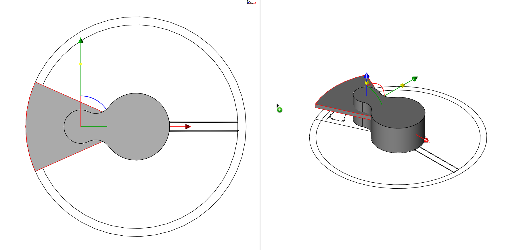
We start out by switching on 2D in top view and start with constructing a series of flat curves. The wheel in question has 15 spokes meaning 24 degrees between them. The green lines and circles are only there for reference helping construction. Note that you can mirror over the center line thus you only need to draw one half and than can use the mirror function to create a symmetrical set-up. I made the center 2.5 mm in diameter and the outer edge of the rim 8.2 mm and the inner edge 7.6 mm thus effectively the inner part of the rim will be 0.3 mm thick. On the right hand side we see the cross section constructed for the wheel taper. One polygon with 0.35 and one polygon of 0.3 mm width. The actual cross section are the black lines between the corner points of both polygons. Important is that these corner points intersect with the inner rim and the center so that there are no gaps otherwise you cannot extrude them to 3D objects. Easiest to handle will be if you group these four lines as single group for easy selection.
The circle for the pin base is offset with -2.05 mm and is 1.25 mm in diameter. This is connected with the center curve using an arc of 0.6 mm. This center part is actually built up as a group of 4 arcs where it is again important to certify that all the end points are connected. You can use the join function for this that resides in the trim functions in the modify menu. The same holds for the triangular sections built from 2 lines with an angle of 24 degrees connecting the center with an arc in between. The two potatoes on the left, that will be used to create the holes, are interpolate splines made with a series of points.
Step 2
 topview
Now the fun begins. We switch on 3D view and use 2 viewport layouts, here you see top view left and right hand is isometric view. First thing we do is create an extra layer for the 3D components using the concept explorer.

Now we can extrude the center group to an thickness of 1.3 mm using the extrude solid function.
Step 3
 topview
We now extrude the lefthand triangular area to 0.2 mm thickness and than move it to a level of 0.6 mm about midplane.
Step 4
 topview
We now extrude the 2 triangular areas beside the center also to 0.2 mm and move these also to a level of 0.6 mm. After that we extrude the 2 splines for cutting the holes to 1 mm height
Step 5
 topview
We now cut the holes by subtracting the 1 mm splines from the triangular plane. You can use several view ports to check your work.
Step 6
 first spoke
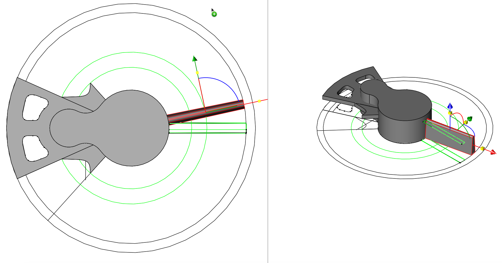
We can now construct a spoke. We start by copying the 2D cross section and move this to an height of 1mm. In order to get a taper in vertical direction we change the width in Y direction to 0.2 mm. We than use the Skin Solid function to connect these two cross sections. Next thing we do is blend the top surface to a curve using a constant radial blend of 0.1 mm. Then we set this spoke in its correct place by rotating it with respect to the center over an angle of 12 degrees.
Step 7
 15 spokes copies
Next produce all the spokes using the polar duplicate with 15 copies with the center as reference.
Step 8
 topview
Extrude the inner edge of the rim to 1.2 mm
Step 9
 topview
Extrude the outer edge of the rim to 1.2 mm.
Step 10
 topview
Subtract the inner block from the outer rim and have a view of your basic wheel. You can now switch off visibility of layer 1 with the 2D parts as we no longer need these.
Step 11
 objects connected
Now it is necessary to create a single object from all the basic components. This is a function that would be called 'creating an assembly' in more professional packages but this is not available in Viacad as seperate function. If you haven't saved your work as seperate file than it is best to do so now before going further. Use the add solid function to construct a single item.
Step 12
 blended corners
Use the blend function to create the curved corners, ideally this is the same radius as your cutter when producing the wheel by milling, any smaller doesn't make sense as the cutter cannot reach into smaller corners. Practical is a radius of 0.15 mm. On the pin center there is now an extra step of 0.1 mm drawn to raise the rods above the level of the rims.
Step 13
 holes for axle and pin added
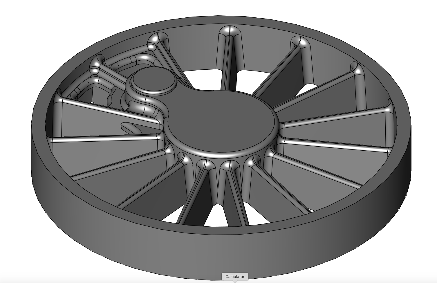
Draw the holes for the pin to 0.5 mm and the axle to 1.45 mm by drawing some cylinders and subtract these from the wheel. The alternative is of course to use a drill instead of cutting them. Basically your wheel is finished except that we didn't draw the balance weight. Thus from this file you can offspring 2 additional files, one for the main driver and one for other drivers with 2 different balance weights added.
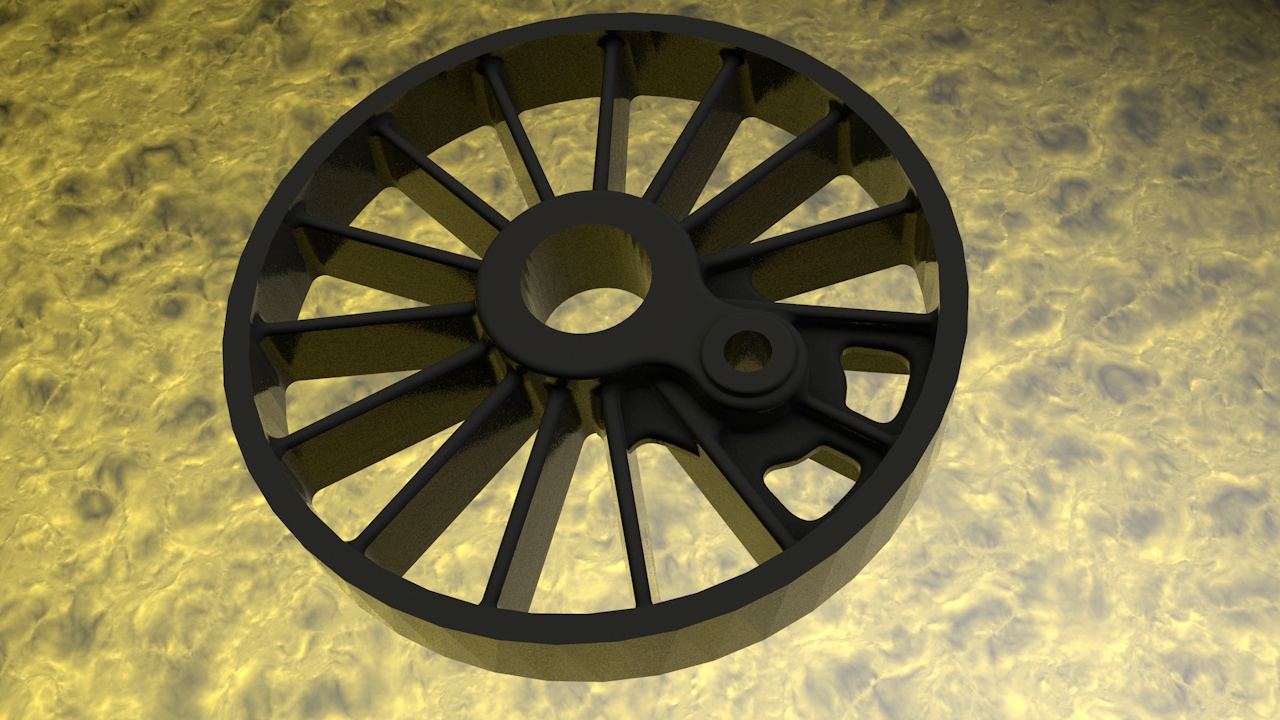 The wheel is exported as STL file that we see here, visualised in a more professional package, floating in a sea of possibilities.
 Step 14
 wheel in Deskproto
The proof is of course in the pudding by eating it. Thus here we see the CNC program generating the paths for the cutter using the STL file as input. This is done with Deskproto. The resulting file is fed to the milling machine.
Step 15
 start of milling from a disc
Here we see a flat disc of black acetal of 10 mm diameter with a 2.5 mm diameter mounting stub on the back for gluing it into a sacrificial piece of MDF. The first cutter is a 0.2 mm V shape cutter for the roughing process. After that we follow with a 0.3 mm straight cutter for finishing. The whole process takes about 35 minutes for a wheel center.
Step 16
 a finished wheel center is waiting below the dust
The finished wheel but with some dust clinging.
Step 16
 see through view
The thing on the workbench flame polished, there is still some (transparent) glue visible attached to the back
 rim loosely added
 3D printed version as complete set for a BR50/52
copyright: Henk Oversloot
date: 3 oct 2016
