
 The subject
A new Fremo landscaping project
Clearing out old modules made space for a new project.
This allows the demonstration of state of the art techniques for an unusual project.
The project
The photo on top shows the subject and a series of photos of the item to be built can be found in the Gallery here: Gellik bridge.
The subject is the Vierendeel bridge in Gellik that crosses the Albert Canal. This railway dates from 1856 and was part of the international railway from Aachen in Germany over Maastricht in the Netherlands to Hasselt in Belgium. It was operated by the Grand Central Belge railway company until this was taken over by the state railway. A bridge was built when the canal was created in the interbellum although the canal wasn't opened until after WW2. The original bridge was destroyed in WW2 and after the war replaced by the current Vierendeel bridge.
This is the longest Vierendeel bridge in Belgium and by shear luck it still exists although the railway is out of operation since 1991. It survived the widening of the canal as there still exist plans to reopen the line. Actually the part from Maastricht to Lanaken some 2 km from Gellik was rebuilt with European subsidy to produce a new harbour facility on the canal. In 2017, 2 years since the start of this page, it is already closed down again, too much burocracy to get licences for operating trains in 2 countries in the same time gap, another perfect example of waste of energy and money in the EU!
There exists a similar Vierendeel railway bridge in Monsin near Liege, but that one is largely surrounded by water as the southern side of it is situated on a dam in between the river Mose and a canal.
The plan

Using Google it is possible to produce a view from above with the arrangement of the modules drawn in. The track radius is 500 m (3125mm in model) and the main bridge and its 2 sub bridges just fit on a module with a length of 1m25. The main bridge is in model some 70 cm long. This module will fit the current car with a few cm to spare thus transport as obstacle is tackled.
A quick impression of the arrangement was done in C4D to see where cutouts in the module sides are necessary in order to built the modules. When finished this group of modules will give a length of 5.6 m of scenic landscape for Fremo use. Maybe obviously but the canal is not modelled to its current width but to its original width to express the situation in the 50-60's. Some photographic evidence of how the canal looked was found from the Vierendeel bridge between Lier and Herentals which was of similar construction but 89.50 m long.

Modules
A special Fremo 'Basteltreffen' was organised by Gerd over Easter 2015 and this saw the production of a series of modules on which these 5 were part. In total we succeeded in producing 10 modules for 3 projects. As it all concerned curved modules the basic parts that will carry the landscape were prepared in advance on a CNC milling machine. The rest was machined in concerted effort under supervision of Gerd in his workshop. He is professional cabinetmaker thus we learned quite a lot on how to join wood correctly.
 The two outer modules will be finished first, they received their painting here, RAL 8011, according to Fremo standard.
The first thing to do is getting the rough things out of the way such as finishing the sides with a layer of paint. This is rough work with a sanding machine and filler creating lots of dust and this is best done outdoor. Therefore I prefer to do this first before any landscape is in place.

At the same time the milling machine was put to work to produce curved track bases from 1.5 mm pcb. This comes from a large sheet that was procured by Hans on one of the Rheine meetings and now sees good use. It is thicker than I normally prefer to use but stock suffices for the entire project. As the modules concern 20 degrees curves only 4 parts of about 30 cm are necessary per module. This easily fits my machine making life a lot easier. The cutting takes quite some machining time but this is easily recovered when track laying commences. The alternative would be to mill a curved template for laying 2 mm sleepers along a curve, less work as you only need a single item but I didn't have enough sleepers to start with. Besides that, these sleepers don't need any gap filling, have the correct length of 16.25 mm and the plates are correct for Angleur-Athus plate work to NMBS drawing.
 The quick and easy part with flat modules with 20 mm XPS foam filling the gaps.
 Cutting and fitting pieces of foam for the higher levels.
 overview with pieces of foam cut oversized for the landscape to fill.
 the foam shaped to fit cross sections with knife, saw and sanding paper.
 covering up with a layer of modelling clay
 gluing the sleeper strips in place on the trackbed
 ballasted track and initial colouring around the track.
 air brushing some base colours along the track, note the track is covered up.
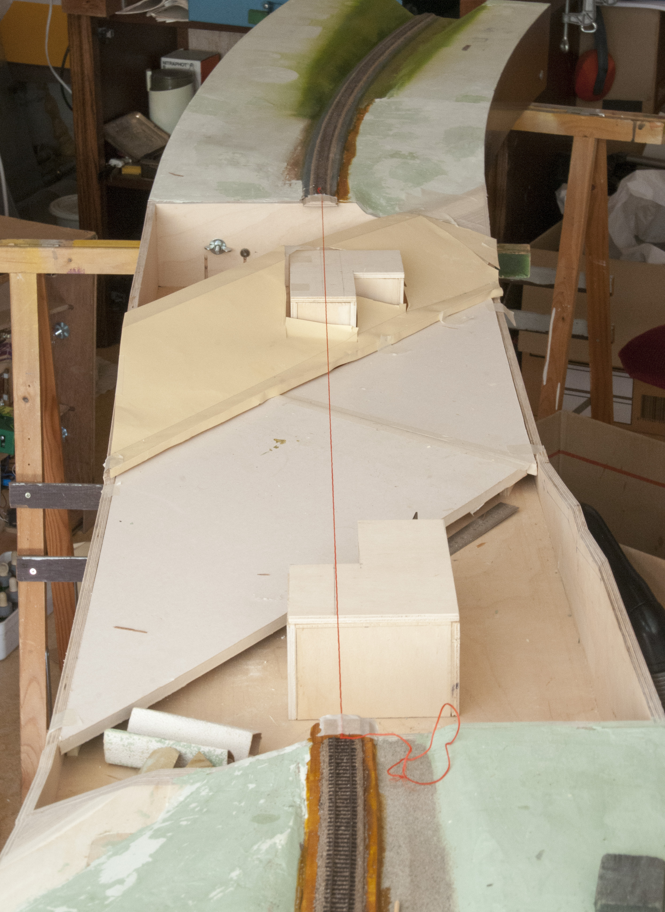 The central module shaped and setting out the roughly shaped base for the bridge. The landscape is filled in with paper and foam board to visualise the situation and to help decide how to built the model. The red string is roughly the underside of the sleeper base.
 This is a cross view showing the slanted angle between the Albert canal and the bridge.

A bit of progress. The water is a sheet of 3 mm ply supported by XPS foam strips with as first approach the water surface painted in greenish black. The concrete bridge supports are shaped into final form including the 4 main towers for defense purposes. These supports are made from 6 mm poplar ply and the towers are made using 1.5 mm plastic sheet. The lot is airbrushed with Vallejo model air primer mixed to a concrete colour as base for later paintwork.

There has been quite some delay in progress as I found the main bridge module to be warped over the shallow diagonal after fixing the water. This effect was due to having only lengthwise reinforcements and the module apparently already warped on its trestles when gluing the water. Testing showed, particularly with the rest of the modules connected to it, that it was very easy to twist the module several cm over its diagonals. Of course this is unacceptable as also the whole bridge would than twist and probably break or come loose of its bases.
This warping was repaired by first removing the water ply and then fixing a cross of 6 mm birch ply to the bottom. But this meant the procurement of a large sheet of 6 mm birch ply and cutting two gaps into each of the reinforcement strips. However this repair turned out to be very effective, the module is now completely rigid and straight again and it sits fully level on a flat surface. (For this type of work a superfluous interior door of reinforced board is an ideal flat working surface.) After this operation the water ply was fixed again.

The southern end is here filled in with pieces of 10 mm foamboard and 20 mm XPS foam that are roughly shaped to the required base form. Fixing is with hot melt glue, which allows fast working. This base will be coated with a layer of modelling clay as base layer for further landscaping.
Mechanically the bridge supports are fixed to the baseboard with a screw from below, allowing removal for final painting (at least theoretically). Two 60 mm holes were bored below the future main bridge supports to allow access from below for electrical connections. The temporary removal of the water ply also allowed to fix a tube between the two bridge supports for electrical connections between the ends as the ply cross now interferes the free wiring space at the bottom.

Here you see the complete module with both sides shaped and coated with green landscape slurry, still wet. This base layer can be painted on with a brush and fills all gaps and slits leaving a good base for grass and other finishing layers. As usual I did run out of modelling clay on a day with shops closed, thus a fresh mixture was home brewn. This is quickly made up with a recipe for enhanced papier maché. The recipe: take a bowl with some water, shred 4 paper egg boxes (without their 6 eggs, preferably 3 yellow boxes and 1 blue one) and use a blender to mix into a fine slurry using a minimum amount of water. Add 8 spoons of green Italian earth ( Terra Verde ) and 2 spoons of methyl cellulose (wall paper glue) and mix again with blender. If the mix is too wet, because you used too much water, than you can drain water by wringing it through a cheese cloth leaving a relative dry mixture. A relative though slurry will of course dry faster and is less prone to shrinkage but it may require a palet knife instead of a brush for coating. This recipe will give about 1 kg landscape slurry which will suffice for at least 4 modules (note: +60 ⁰C heat treatment is necessary for long term keeping when wet). If you want different colours than select different coloured egg boxes and use different pigments, but brown umber looks to me the only reasonable alternative, particularly for wooded or fallowing terrains.
 Overview with most of the rough work done.
The above photo shows the state of the art with the concrete parts all shaped and painted and the landscape got a base layer of paint and turf. I now have the choice to either start with the steel parts or first go on the landscaping route. Experience tells me that doing the landscaping first is the better road to end up with finished modules. From here I can work from the canal in the center towards both ends. This ensures that a homogeneous result will be reached, even if I run out of a particular landscape material that has to be replaced by new stuff, which invariably comes with different colour/texture. In total it concerns an area of about 2 m², which is quite a surface but lucky most of it is more of the same. The steel parts complete with rivets look a relative straightforward job to produce. Also some trials with stock and camera show that including some 3 m length of sky boards into the building order won't do harm as this will avoid extended photoshopping to clean-up a disturbing background when photographing stock running over the bridge.
 Rough static grass applied with longer grass the further from the canal. On the approach the surfaces were prepared for further decorating with ordinary waterpaint colours in olive green and brown umber.
 The right hand embankment first got some higher growth at the canal side, than the grass field was done in mixed blend of static grass and after that the inner embankment was covered with a mixture of selected ground foams.
 Here the strip between embankment and grass was covered with higher growth, things like brambles using the bushed area method and a series of tree skeletons was prepared for planting individual smaller bushes. On the left static grass was applied and that embankment will get similar treatment.
 First stage completed, this will do for the time being and further detailing can be done after bringing the northern approach to the same level.
 This is how a close-up looks with some stock on it.
 The northern approach is now brought into the same state of landscaping as the southern approach.
Until now for Gellik 4 batches of commercial flock were reconditioned into a better colour and size blend using gouache and coffee grinder and 2.5 bottles of hairspray were used for fixing this on all the bushes. The hairspray however does make the colour come out a bit darker than intended. Contrary to that the amount of filter material coming from that big bag of pond filter wool is neglible.
Reaching this stage means that I can now start to produce the plan for constructing the main item: the bridge!
Bridging the gap
Principally the bridge will be produced using white polystyrene but because of its length the idea is to built the bridge around two metal beams with similar model dimensions as the real thing. My main concern is not strength but to avoid distortion and keep the track flat and straight. The plastic will be strong enough, in fact it will probably be stronger than the real thing. As metal H-profile was clearly a factor 4 overpriced at the metal detaillist thus 3 massive bars of 6x3 mm of 1m length were obtained instead. These bars were screwed together at roughly 20 cm intervals using nylon distance pieces for insulation and M2 screws. The track is glued to these bars with 2 component epoxy and connected either in the center or on the end for the 2 outer bridges using tiny pieces of brass with 1 x 1.5 x 0.8 mm dimension, pretty close to not visible. This construcion hopefully allows for enough thermal expansion, bars and rail will have the same thermal expansion but the plastic is probably a different case. At the same time some small gaps of minimal 0.5 mm in total are necessary to be able to take up at least plus 15 degrees thermal difference in case it is getting really hot (e.g. in the car during transport or in the sun behind glass). In order to allow for vertical alignment the outer bridges have some legs with M2 nuts to fix it to the base. These are also used for the electrical connection of these 2 parts. The big center part will be fixed rigidly with M4 thread and nuts in 2 perspex keepers.
The inner core of the 2 outer bridges were produced first following the usual process of drawing them up and using the milling machine to produce the parts in 0.8 mm PS. These simply clamp around the metal bars although when completely finished the bars can no longer be taken out.
It is a tab and slot construction which makes it very rigid.
Straight track was produced using specially produced track jigs. These are milled from Trespa and have 2 lengthwise grooves for the rail to sit on top of the sleepers in exact the right place. This jig allows to produce straight lengths as long as the available rail. The center part of the bridge is about 78 cm thus in this case 2 code 40 rails from MEC were used, these are about 90 cm long thus there are no unnecessary rail connections on the bridge itself. This rail has a bit wider foot than the rail of the 2mm SA (1mm vs. 0.85) but in this case a larger surface area for solder is probably better in view of rigidity.
 track jig for straight track and a piece of track for the outer bridge produced in it.
 View of cross section of outer bridge.
On the above photo the 2 brass bars and one of the white nylon distance pieces are clear to see. The white wire is the centerline spanning the 2 end boards over the top of the sleepers. This allowed to measure the exact height for the 2 stands with M2 threads replacing the white piece of ps on which the subbridge sits here. The turned nylon distance pieces on the outer bridge ends were replaced by 6.5 mm wide rectangular blocks milled from Trespa by which the main bridge now automatically slots to its outer bridges. Thus in horizontal plane there is no need for any adjustment to align the track. The landing end of the bridges sit in a 3 mm thick piece of perspex with similar cross section to that of the bridge these are screwed to the end board. These parts have a slot to allow for adjustment. The outer cladding parts of the bridges all still have to be milled, these will carry the railing and then there are still multiple tens of thin strips to apply for detailing on simulating the various I-beams instead of the flat material it now shows.

Here the central part for the main bridge is in place, when connected this allows to cross the gap. Now its time for making a detailed drawing of the bridge itself. One of the photographs I made was a sideways view that was perpendicular to the bridge from the higher embankment. Together with the known main dimensions this photo allows to produce a drawing of the bridge. Remarkably only a 0.5 % difference was calculated between the 2 ends thus that photo is near perfect. Towards the ends some corrections are necessary due to distortion but that is easy to compensate. Producing these drawings and a strategy for the tabs and slots in order to make a rigid construction will take up some time.

 The result here seen still on the machine but with the newly cut openings taken out for contrast.
In this case the main parts of the bridge are longer than the machinining length. In order to mill these use was made of a straight edge and a reference pin. The straight edge serves to align the material and the reference pin allows repositioning over an exact length dimension. For this job I replaced the normal aluminium machine bed with a (reasonably) flat cut-off of 18 mm sacrificial MDF which takes up any cut through the material thickness without damage to cutters or material. The straight edge used here is a length of 3 mm thick acryl, which is positioned parallel to the machine axis using a round pin mounted in the collet for alignment and 2 pieces of very well sticking double sided tape. The first thing to do is drilling the pin holes in the baseboard and accordingly in every sheet of fresh material. These two pin holes and straight edge function as references to move the sheet linear over a dedicated distance. In this case these reference holes are used in combination with mirroring of the X-axis, thus a drawing of only one half of the bridge suffices while symmetric. This technique can be used to mill unlimited lengths of drawing but more practically as long as the available material, which is generally longer than the capacity of your machine. This alignment technique also allows you to produce double sided milling products as you can simply mount the parts upside down using the same reference holes with 100% exact alignment.
 The 4 main carriers, 2 inside ones with notches and 2 plain ones.
 A view of how the inner parts do connect up with the rail carrying bars
 Doubling up the sides into a single unit with strips and profiles, in front a turned pin to fit the reference holes aligning both sides during the gluing.
 test fit of the main components on the module
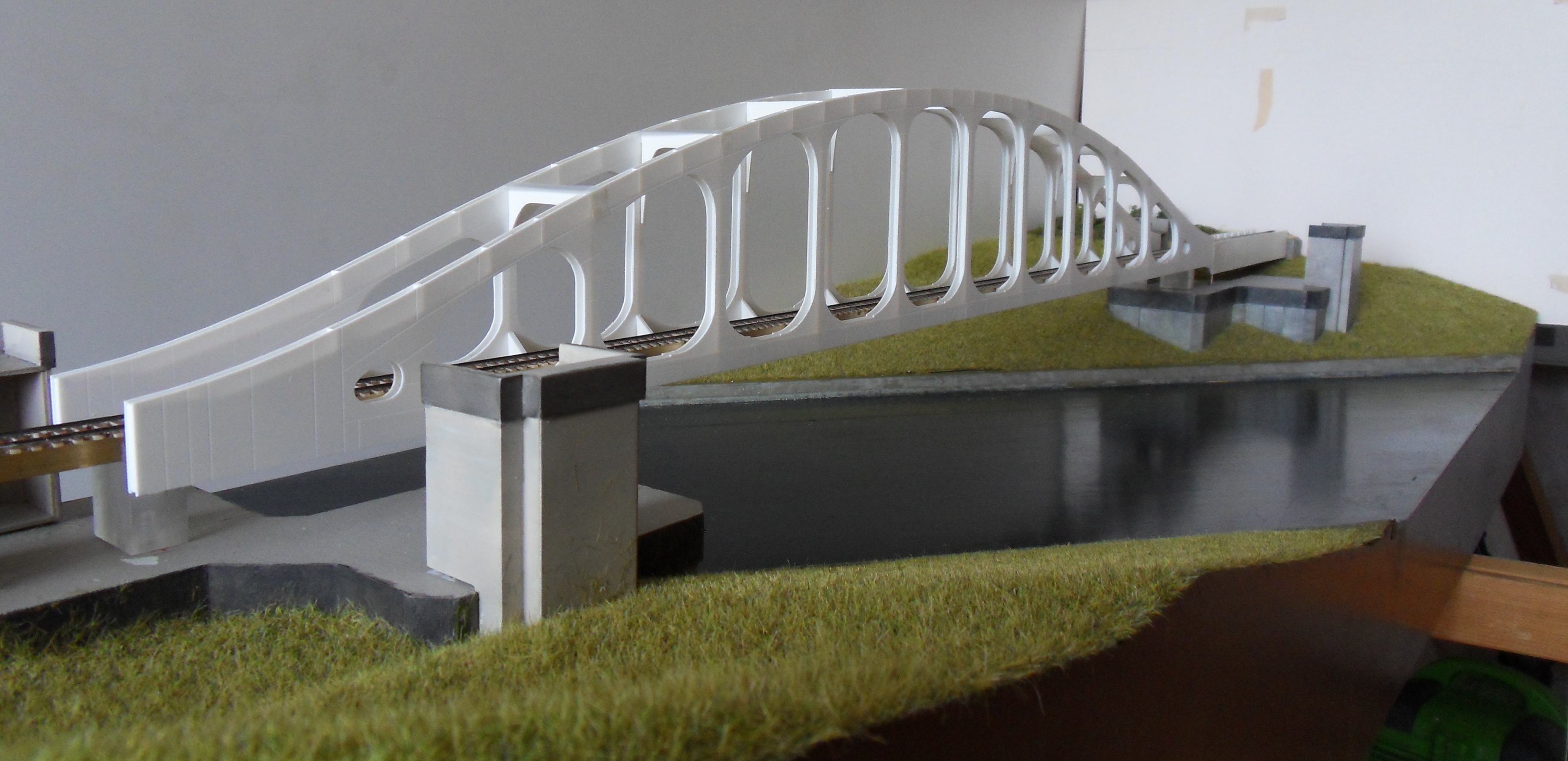
 side view
A milestone reached!
The above views give the first impression how the model will look. The parts are temporarily secured together with some tape, all the strips and rivets still have to be added and that is simpler to do with sides still flat. But that is a job that can wait till next modelling season. But now it is possible to check and try the crossing with some trains and take this project into use on the next Fremo meeting.
I did built a dedicated transport box for this module that nicely fits the module complete with bridge. Only legs for the module are currently still failing.
copyright: Henk Oversloot
updated: 10 May 2019
