
Unextending a layout
It is relative easy to extend a module with an extra piece, but can it be undone?
Obtaining a smaller CO2 footprint incorporated a smaller car. When your layout no longer fits the car than something needs to be done.
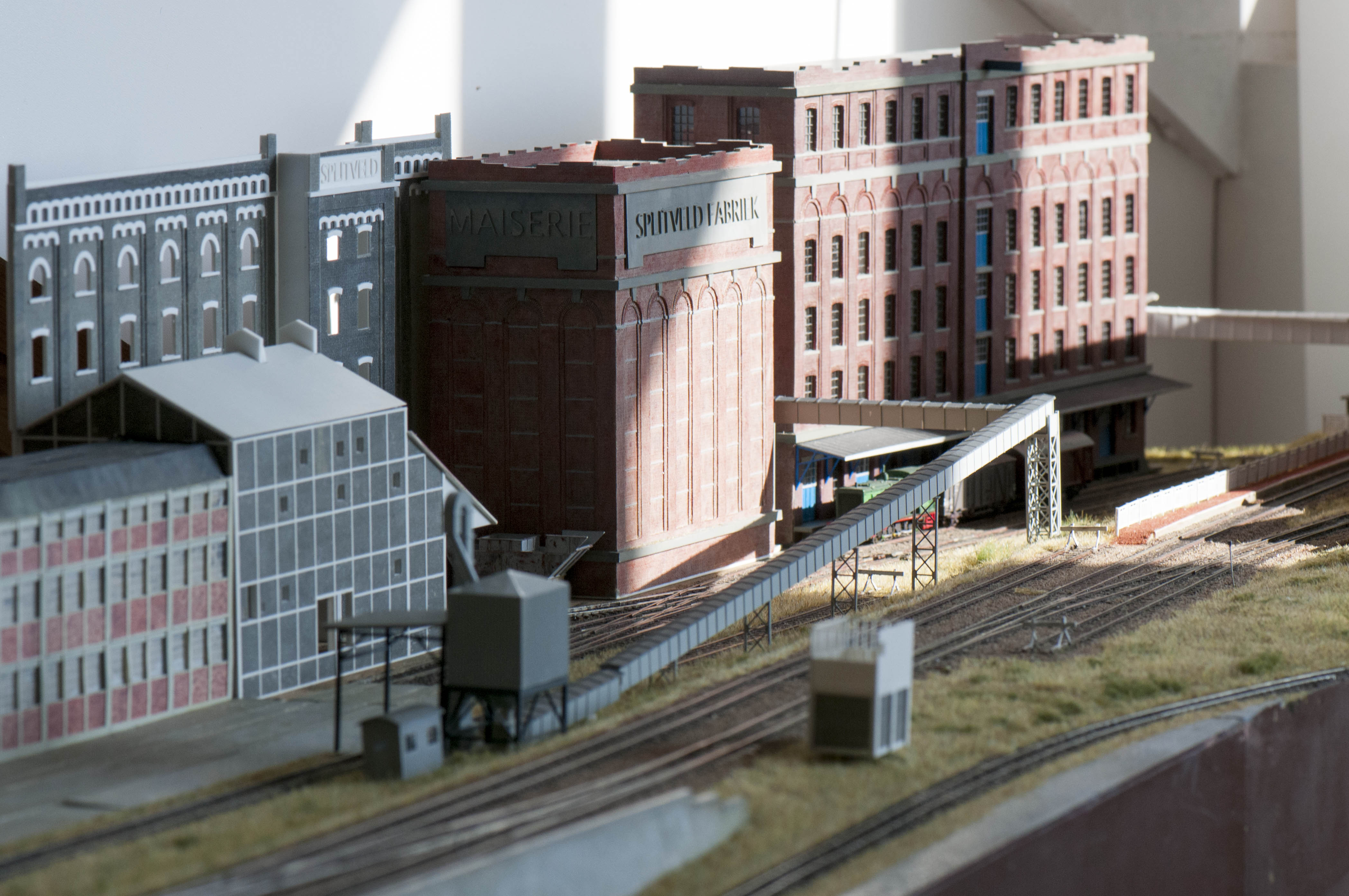
The sixth incarnation of Splitveld Fabriek
After measuring the new car several times it was entirely clear that the longest item that could be accommodated was about 1m40. However the central piece of Splitveld Fabriek was 1m50 after it received a 30 cm extension which formed its 3rd rebuilt some 15 years ago. The reason for extension was that I found the existing tracks too short and later two points were planned just on top of the joint. Originally the base layout started out with a length of ply of 1m20 and there was still a cross member left that was once the end of the layout. After a refreshing holiday I just took the jump and decided to cut the layout. The track was lifted over the joint and some scenic items saved for reuse. A large hand saw was excercised to make a relative clean cut. This left me with some open ends.

A photo of the remains after cutting. The cut along the cross member showing the original hand grip and it also shows that a cut along the front was made at incarnation #2 when the wall was added.

The above photo shows the remaining pieces, two small orphans of about 30 cm each which were part of incarnation #3 and #4
Replacing the cut parts
Its fifth incarnation was an extension on the right hand side. This involves a major production stage for some new buildings: large brick buildings. The construction of more buildings is in planning. However on transporting modules it is easier if you can stack modules on top of each other or transport them back to back. Therefore items preferably should have a similar length. Thus instead of trying to salvage the 2 short pieces I decided upon an entire rebuilt with the same length as the right hand module, which is about 95 cm long.
There was no desire to do a major redesign of landscape or track lengths thus I made a similar design in 3D to see how this would work out and where to put the reinforcements to built a sturdy module that is not too heavy.

New design along simular lines including a small viaduct and a stream

The underside of it
Woodwork

Excercising the clamps on laminating the curved sides from two layers of 3mm ply.

The major part of the woodwork finished, now it is planning where to reposition the existing points
The hand hole in the original baseboard header was first filled with a fitting piece of ply as doubtless some screws for fixing needed to be placed there. After that a selection from the available ply was made and cut to size for new module headers and a T-bone rigger to the position the main track upon. The whole lot was placed on a spare door to obtain a smooth reference plane for measuring and getting everything square. The headers for the old and new part were cut to the required cross section and than combined using dedicated register pins and glued to the original main board. After that the new module was built using the prepared ply parts. Waiting for the glue to dry took most of the time.

based board sides coloured RAL 8011
One important thing to do is a priming finish of the sides. Because this is rough work, filling with primer and sanding with a machine will ruin your landscape thus you have to do this before landscaping. Also with an initial paint layer the whole module looks much neater which is good for moral.
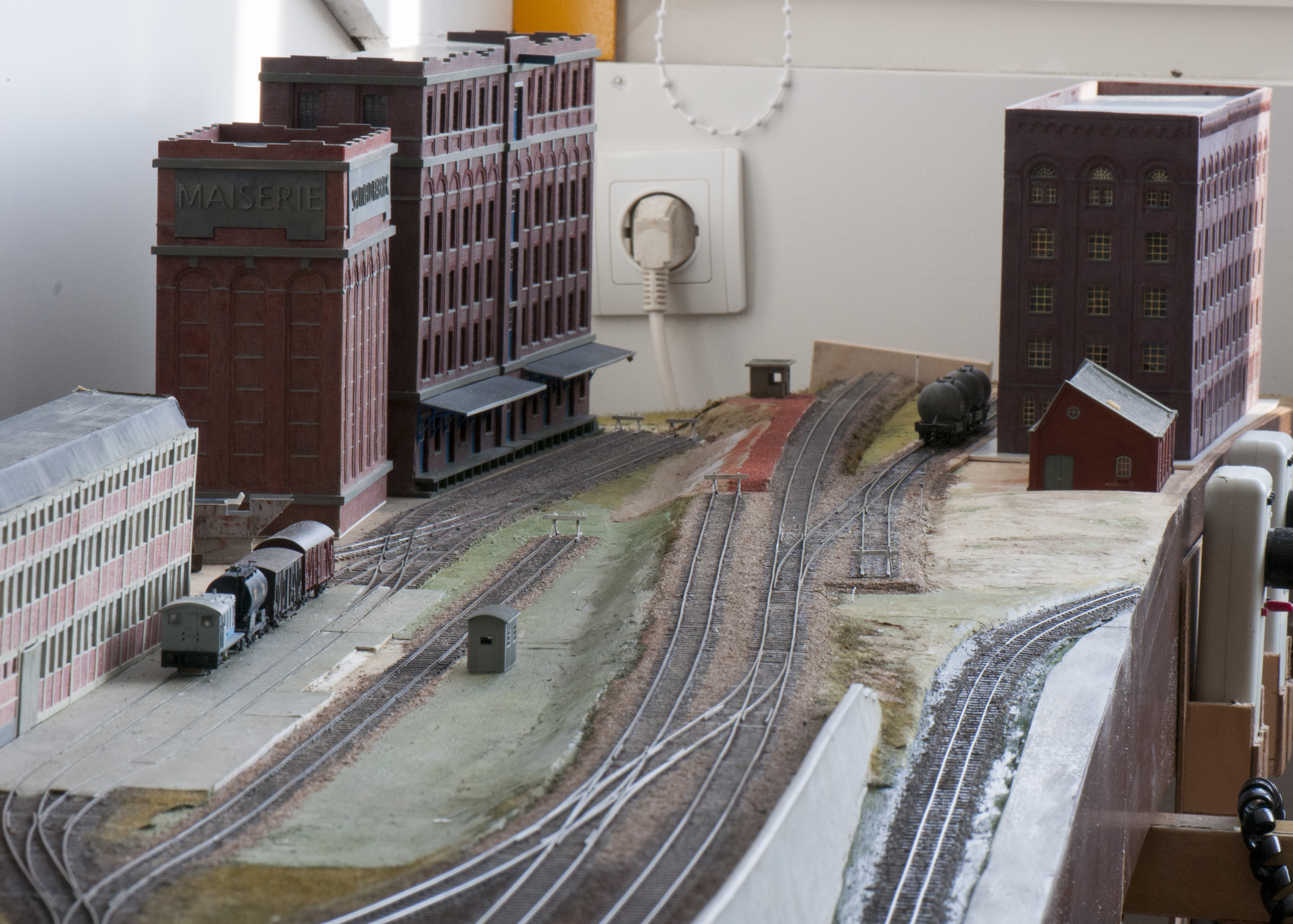
reconstruction of the track

picture showing the completed track work, track planing device still lying in front
Most of the lifted pieces of track could be reused, this saved for instance building 2 points. Part of the failing main track was reconstructed using milled sleeper bases. This saves the timeconsuming construction of building track on plates with individually cut plates. In the milled sleeper bases these plates are integrated. Although this saves time I found that a problem with milling these bases is that the base material that I used doesn't keep flat. I needed sleepers to 1.1mm high to be compatible with the old sleepers. Thus 1.5 mm single sided epoxy copperclad board was used, but this shows a small curvature which gets enhanced if you make it thinner. This leads to small height differences of the sleepers over the length of the base which somehow have to be evened out. This was done by planing the final track using a 20cm piece of wood wrapped in 800 wet and dry to remove any undulations as far as practical. 
This picture shows the pinning of the bases at the end of the board to prevent transport accidents that lift the track.
The end of the tracks are pinned with 1mm brass pins drilled through the plates to prevent incidents on transport. A 0.75 mm hole is first drilled some 10 mm deep, than the hole through the sleeper is enlarged to 1 mm and a pin is hammered home and cut off with pliers. After filing flat this can be soldered to the plate.
Constructing the landscape
Besides some trees it is probably easier to built the landscape entirely new instead of trying to salvage the existing landscape items. This will also get rid of the somewhat dusty appearance of the grass which developed over the last 15 years. This reconstruction work will evolve in the coming weeks.

The viaduct still under construction allows shaping landscape
The viaduct is constructed from 1mm ps sheet cladded with some Slaters plasticard, the same type as used for the wall in order to get cohesion between the various modules. The thing is built in 2 sections that were glued together on site as there was no way to fit it as a single piece without enlarging the opening in the T-rigger. This viaduct is roughly based on the ones found along the Bock line in southern Belgium. These however show coarser rough stone sidewalls and I will also skip the steel railing on top as this will be too damage prone in transport. Instead I made the side walls a bit higher which will get a hard stone ledge on top such as used on the wall.
The landscape gets its form by filling the big openings with 10 mm foam board. The rest is filled in with 1.5 mm mdf sheet. This can all be shaped using a sharp knife and glued using hot melt glue. This allows fast progress. The other openings can be easier filled with a shaped piece of hard foam.

A view in the other direction

Landscape coated with a slurry of model clay to close openings and to smooth and even out edges

Green base coat with acrylic paint

A basic treatment with static grass as start before the final landscape painting and colouring starts

Track is ballasted and also weathered here, the grass got its first treatment

Progress photo with landscaping the area around the viaduct, here not finished yet, but click on it to get a later update larger view.
The viaduct was finished with some strips and the stone ledges added, after that it was painted and weathered. The first part of the narrow gauge track was rebuilt using 2mm SA code 30 strip rail and home cut sleepers. The stream filled with Woodlands plastic water, made muddy by adding pigment powders. See a more streaming flow visualisation on the update, made by treating it with a soldering iron. The bush and undergrowth are made from scouring mat with sheep wool and ground foam sprinkled on top, glued with hairspray.
Another new building

A new building in progress based on SCAR in Hermalle sous Argenteau using the same techniques learned here: large brick buildings.
A picture showing about half way progress on a new building to replace a much too coarse commercial one. An action that has been on the to do list for a smallish 20 years! The building is sited along the railway and river Maas (Mose) between Luik (Liege) and Maastricht and it occurs on various railway photos in the background, which is how it drew my attention. Thanks to Google you don't have to leave your home nowadays to produce a model. You can view it from all sides without leaving your armchair. You can see it here:
Road side view of the building that shows the modelled facade parts best
There exists a highly similar style building in Beez , some 100 km further up the river Mose close to Namur, differences exist in the ground floor and the way the deeper laying bays connect to the ground floor as the ledge in Beez fails and that building is one story lower.
The place where this it to go on Splitveld doesn't allow the entire building but as the style of the main facade with its raised center part is very characteristic another more complete copy may finds its way in due time. I contemplate to produce a silicone rubber mould from these facade parts to produce copies.

Rubber moulds from the originals

Some painted copies
Although the first copies were not ideal, the resin dried too fast to chase any bubbles as it was actually too warm for this sort of thing. But these copies lead to the above result, which is good enough for playing around, certainly considering the time saved. The light wasn't good thus these colours look a bit overdone but with another washing it will all blend nicely. I will test the idea to mix in some red pigment powders, this will help hiding all window openings and small corners and edges that are difficult to paint. The alternative is of course grey but any dark colour is better than the original yellow resin. The painting is done in stages, first a grey base layer for the courses and followed by wargame acrylic colours, mainly a mix of red with some blue, in drybrushing technique with a relative large brush flat along the surface. Some wheathering with powder pigments. First I will try to produce it into a square corner by cutting some 45 degrees edges on the back and add some floors and roof for rigidity.
A typical example of how a layout grows organically
Although I only planned a small building to replace an old facade, the fact that having the moulds readily available simply cried out for more. Producing a building the size of the real SCAR is a painless process of making more copies. On the following picture you see the process of it coming together, casting copies doesn't take more than an hour per set of 2. Here I added a blend of 2 reddish pigment powders into the A component of the PU before the final mixing. By filling the moulds in 2 layers the chasing of airbubbles becomes a much better controlled process of brushing suspect locations with a flat brush (cleaning the brush in time with acetone!). The castings come out lots better now and are mostly free of airbubbles.

Appletree models in action, modelling outdoor with perfect weather in the shade of the apple tree with a cup of tea. Here we see new castings laid out for preparation of further glue work.
Modelling outdoor with perfect weather in the shade of the apple tree. Here I am preparing a range castings for further work. This means removing films from the surrounds of the window spaces and smoothing the back of the castings to take the windows. This is dusty work which lends itself perfectly for the garden on a nice summer sunday.

The main parts glued together

A visual check on the layout
This picture shows a check how the final lot can be fitted. Adding a sort of main entrance wouldn't do harm, as well as another rail connection and a loading dock at the railside. Of course this is all but a planned action, more the result of on going progress driven by a slumbering wish to do something with this SCAR facade. Like everything done to this layout until now it just stays an organically growing layout. For shows something like a view block would be nice when viewed skew between the buildings. I am thinking of a conveyor belt to connect the two and maybe put a mirror angled at the back so that you see the back facade of the building at the front.

Assembled building with windows completed, roof details still waiting. On track the pilot 603 railcar
Lots of hours later for painting the facade and cutting and finishing of the windows. For painting such large buildings you have to count in days not hours.
The main windows differ from the small building in number of small sections. A time saving measure as with plus 200 windows this sort of details counts, apart from that it visually distinguishes the buildings. Note the visual difference between the 2 buildings on this picture which originates from the colour of the window frames. The front gives a much lighter appearance than the dark mill at the back. The to do list contains finishing with the details on top corners and the building with watertank on the roof, also some drain pipes can help to hide the seams between the components.
You can not look into the building because of the blackish backing paper behind the windows, this saves lots of interior detail. In practice the floors were filled with endless rows of machines all sieving, pressing, milling, cooking etc. to produce oil from the grains and process the remains to feedstock and food in a top down approach making use of gravity from the upper stock downwards.

A depth of field photo showing the state end of december after the major track alterations. The narrow gauge is also entirely reconstructed here, but still leading nowhere.
The recent changes involved laying a new connection to the SCAR building and straightening the track in the lower yard to prepare for unloading grain wagons.
Several track changes were carried out in this part too. The main track did get a new connection to the SCAR building. This work also allowed to remove the undulation over the module connection in it. The siding in the lower yard was straightened and now crosses the module connection. The unloading section should come close to where the corrugated hut is standing. All failing buffer stops were constructed, 6 of them, using steel bullhead rail.
With the new SCAR building the platform and shelter were in a bit awkward postion thus these were shifted to the end of the buildings. The fences for the platform are in preparation and the gravel on the platform is still wet here, this needs some blending. I replanted the hectometer posts but the buildings and railway also need to be fenced in too. Also we can start with some further landscape work to grow some new grass on the bare spots. This will greatly enhance the view, getting rid of unfinished looks. Thus there is still a lot do.

The grass grows fast in Splitveld, first phase taking some 4 hours of planting carefully blended fibers in selected order.

Started with the fences along the platform

Testing some loading equipment.
On the above photo the fences along the platform edge are in place. The loading rig at the SCAR building is soldered up from brass profiles with a turned silo from pvc. The frame fits the minimum gauge width but with hindsight I think slightly wider would have looked better. Not shown yet, but in the mean time this is repaired by inserting several mm U-section in the top beam after cutting it in two. Apart from having to mill an extra length of U-profile with the same offsets this turned out to be relative easy.

Enhancing the installations with conveyor belt for unloading the grain wagons
A photo of further installations all still loosely fitted, the rail installations are based on photos from Leuven showing a rig close to the large brewery of Stella Artois. This was a piece of Leuven that disappeared for the new ring road. The cladded convoyer belt is based on other photos from locations that disappeared elsewhere in Leuven. The rig is partly soldered up from brass profiles and all the white pieces are an exercise in plastic. A paint job will do wonders here and then imagination can make up the rest.
A test fit for the last buildings filling the gap in the back
The facade in the background is based on the buiding of the farmers cooperation 'Boerenbond' in Leuven, the foreground is based on the lower photo and stood once upon a time in Tilly. Note that the conveyor belt and loading rig now carry some colour but still lack weathering. The fuzzy foreground shows a small signalbox coming into being.

The original in 1993 in Tilly was part of a large and pretty long building. It was already abandonned at that time. Note the thick layer of moss on the corrugated roof overhangs.

now with a first layer of colour on it
The colour on the steel framed building came out darker than wanted although in daylight it looks less brown and a bit more reddish than on the photo above. Probably due to using led light while painting but we can always do a repaint in summer time.
copyright: Henk Oversloot
date: 6 april 2014
updated: 21 april 2014, 27 april 2014, 11 may 2014 ,19 may 2014,
30 june 2014, 17 july 2014, july 2014, 11 sept 2014, 3 jan 2015,
12 jan 2015, 25 jan 2015, 12 feb 2015, 23 feb 2015
