
An exercise with the modelling tools
Visualising a model of the class 85 diesel shunter and printing it
This article is about building up experience in 3D printing with the Anycubic printer and using a computer on saving time in producing a new model.
Method: Design and 3D print

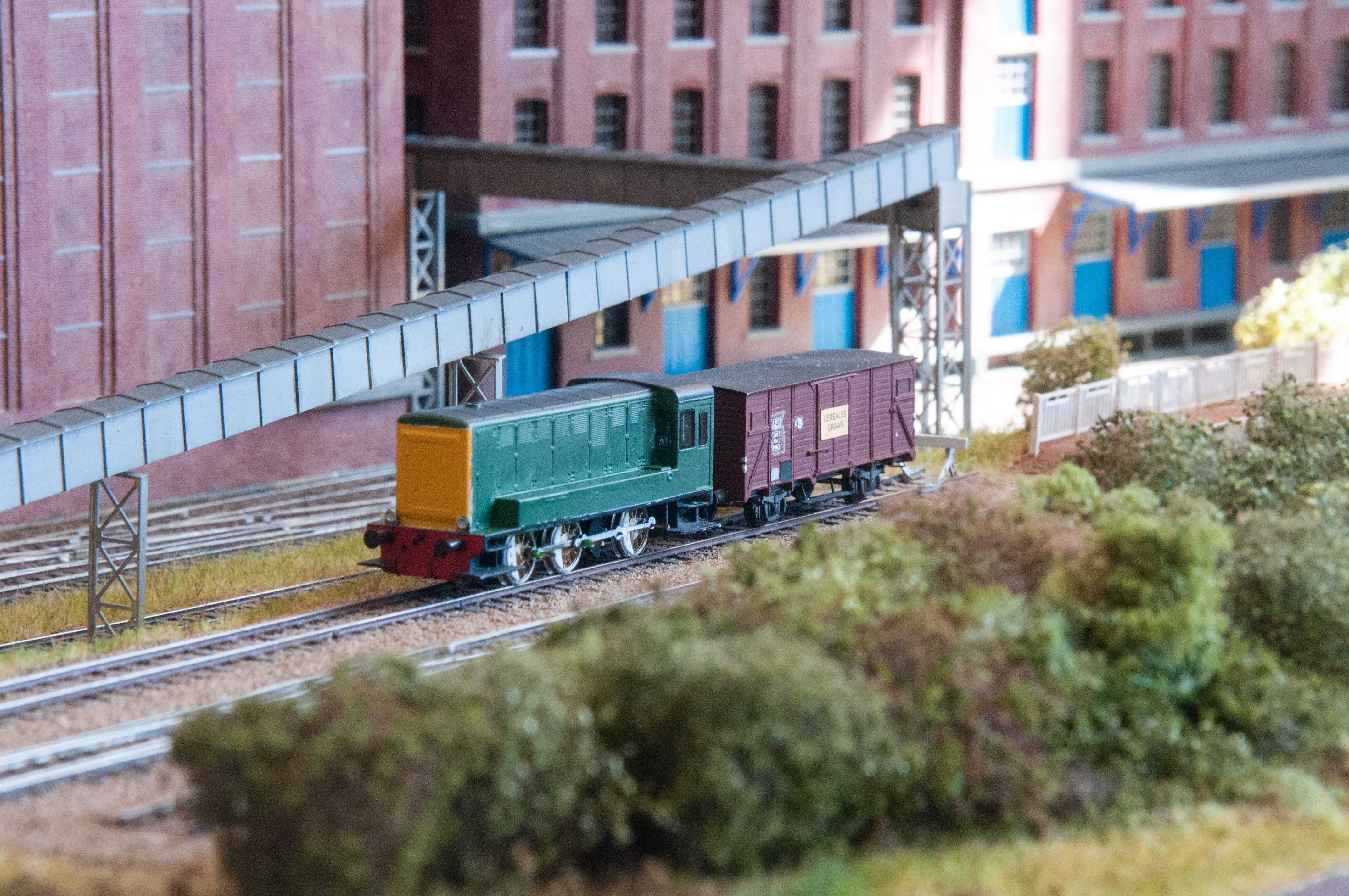
The first trial print of a class 85 Belgian diesel shunter.

The first trial print of a class 85 Belgian diesel shunter.
The choice for this model was just because of the dimensions were already available, it dates from 1956 and these machines saw mainly use in Antwerp harbour. Both its overhanging roof on the cab and the struts on its front are details that make it a useful starter for building up experience with the printing process. Actually I have more use for a class 84 shunter which saw wider use over Belgium. The class 84 has a slightly higher motorcompartment with both sides having identical louvre doors and the cab has rounded roof edges. The body is designed in C4D and printed on the Anycubic Photon with Monocure grey resin.
Clearly there are some errors in the first print attempt, but on the whole this looks pretty useful. The outcome is robust and it also shows the fine detail in the louvre doors in right hand side! Where the layering errors precisely are generated is not entirely clear at the moment, it can be either the STL interpretation or the 3D sliding software. The Anycubic 3D slider output shows some spurious layers on the inside of the cab, precisely at the heigth of this deformation visible on the outside. Thus some cleaning up of the STL file is necessary, but even such as it is now, this result could be used with a little bit of hand work with cutting, filling and sanding.
C4D doesn't come up with meshing errors in this particular area, although it showed some minor manifold errors elsewhere. I used to have something called Nettfab, but this doesn't run on my current OSX and seems no longer free open source. Thus I now tried checking the STL file with a repair program called Meshmaker, which does run on OSX, but it literally pointed to 100's of problems over the entire surface, however none in the area where the layering error seems to originate. Thus all-in-all this is a rubbish program as the printer obviously doesn't have any problem with all these supposed errors. My conclusion was that we have a specific Anycubic slicing error here, and it can be easiest traced by inspecting the slider output beforehand. The image below illustrates the forming of it.

The error can be seen developing in the LCD viewer layer 1087 is OK but layer 1091 shows the inside cab filled but it should show only a circumferencing wall.
Eventually it was repaired by retrieving incremental save #2 and redraw the inside of the cab before its boolean subtraction from the outside. This solved the slicing problems and the resulting cab part was copied into the latest version #19 without any problem. Simply another feature of the Anycubic slider to account with and careful inspection of the slider output before sending it to the printer can trace such errors.
The latest drawing iteration #19 with everything in place, details are accentuated by increased depths around the doors to enhance the visibility in the print. You can control the slider with your mouse to any in between position for inspection of the model.
The trial print serves the purpose of seeing how the body comes out and where changes are necessary. A first conclusion is that the model comes out pretty well and the chosen wall thickness of 0.8 mm seems OK. Particular the corner stand between windows of the cab look to be robust enough to survive handling. The second conclusion is that surface detail such as the doors need extra accentuation for better visual impression, otherwise these get lost in the noise of the 3D print, which is softening the sharp edges in the print. Amazingly even the tiny steps in the louvre doors on the left hand side are visible in the print but this only under the right oblique lighting conditions.
The next question to answer is whether to include the footplate and buffer beams on the main body or keep these as seperate item.

front of Belgian class 85 diesel shunter.

righthand side of class 85 Belgian diesel shunter.

left side of class 85 Belgian diesel shunter.
This new outcome looks a quite useable result, although there are some items to note. First of all the placement of the support structure is far from optimal, this is the best I could generate. The support placement is a sort of random process with lots of misses and few hits. It helps trying to rotate the model over a few degrees to influence the positioning. Here they are all on the inside, but they overlap the line of the footplate (its widest point but with only 0.05 mm). I hope this can be repaired by sanding these struts away. The best way to avoid this is, is to also draw up the support structure in CAD for keeping full control. A certain minimum vertical angle is necessary to prevent needing struts on the roof overhang and the 2 beams on the front of the cab. Strut density here is 35%, higher gives a crisper result on the lower edges, but also leads to having more cleaning up to do. About 1 strut per 3 mm perimeter as rule seems a good approach, actually most of the struts on the inside can probably be dispensed with here. Another Anycubic slider feature seems to be the underestimation of the total printing time. The slicer software predicts around 6 hours, but the printer clearly shows that it will take a good 9 hours and of course it really didn't finish faster. The printer does work unattended thus its not a problem and it doesn't make any noise.
The positive side is that even the very fine door grills on the righthand side come out crisp and complete. Don't ask me why we see the horizontal thickness reflected on top of the tank, but this is very faint and I expect you won't notice it after painting. There is a bit of layering visible on the left hand side, but if the primer doesn't hide this, than a treat with fine emery paper can smooth that. Building this model from scratch by cutting metal and scribing/milling or alternatively etching and soldering would take weeks longer than producing this 3D drawing. Also that way would probably not lead to such fine louvre doors on the right hand side, those on the left however are quite feasible to obtain by milling.
Of course if you want to produce several identical models then this is a good route as another run only takes some cleaning time for the printer and there probably will fit 3 on the platform. All in all an useful exercise.

cross section of frame to be built
For finishing, the frame parts can be a straight copy of the class 80 diesel shunter, well predating the digital age thus there is no documented article available of that one by lack of photographic evidence, but it is of a similar construction, a massive frame with split axles, such as that described here:
V36/type 230 diesel shunter
This one needs 8 mm wheels and is several mm longer, it will get an 8 mm Tramfabriek motor. It is probably large enough for fitting a sound decoder as option.

new frame for testing
Except for the class 80 all 6 wheeled Belgian diesel shunters shared the same layout for frame and wheels, which means that the above frame can be used for 9 different shunter models, each with at least 3 liveries/varieties on head lamps, but the exact number is more a case for colllectors not for modellers. The class 84 already had 3 main batches, the one developed below concerns the first batch in oldest version.

fretting the rods

rods set free
A set of rods was fretted with a jewellers saw from a predrilled steel plate which was large enough for some spares. This is the standard method using 2 pieces of 0.5 mm packaging steel soldered together to obtain a pair of identical rods. I didn't bother to connect the front and back over invidual pins. The short ones are not functional anyway as the holes will be opened out to drive both wheels over the gears. The long ones also drive the blind wheel (jackshaft for some of you). These blind wheels were turned on the lathe from a piece of Delrin and finished by milling. The throw was set to that of the 8 mm drivers, which was measured in situ and found to be 2.07 mm. To measure this first set them horizontal in opposite positions and measure outer and inner distance and than rotate the wheels 180 degrees and again measure the distances. Calculate the difference of each set of dimensions, divide by 4 and its average will give the effective throw. Of course for accuracy first calibrate your digital caliper using a near known dimension such as a drill shank measured with a micrometer which is an order better.
Test runs on the bench with the new rods and the blind wheel (jackshaft for some of you)

test fit of body
The body was freed from its 3d construction ladders using a jewellers saw and cutting pliers. The ladders in the center could be easily ripped off with normal pliers. After that it only concerned straightforward cleaning and smoothing the connections using sanding paper strip files. The plastic is relative soft and easy to smooth. After that a test fit showed where the frame was to be adapted for a good fit, that are the areas in the red ovals in the sketch on top. With help of a jewellers saw the metal part holding the wormwheel was shortened as well as the end of the frame in that area was lowered by some 1.5 mm. On the above photo it sits on the correct height. Permanent fixing needs some further thinking, also a small slot for taking up the backend of the MFK coupler in the frame is maybe be necessary. Of course some extended modelling in 3D will such get right from the start but at the moment producing a frame is actually an independent 2D operation where as the design of the body is done in 3D. Adapting the frame with a saw takes only some minutes thus is the fastest option unless you need more than a handfull loco's.
The class 84 as offspring
The above video illustrates phase 1 as an example how such a design is developed. This concerns the class 84 diesel shunter with the basic form of the body, all details still have to be added here.
Of course this model profits from the earlier experience in design for the class 85. This effectively concerns the order of operations on how to construct and assemble the model, this certainly makes a difference in the ease with which you obtain the end result. Instead of sculpting a cube into the wanted form by adding that what fails or subtracting that what is superfluous, the class 84 was built up with individually shaped components and united into a single body: sidewall, 2 different radiused parts for the roof of body and cab and a short copy of that same body cross section for the end of the motor compartment with additional bevels added. The basic cab form is constructed from a quarter sized cube with chamfered corner and then mirrored over 2 planes.
Above surface details are added mostly by cutting and extruding faces and adding blocks for doors and louvres or subtracting blocks to cut windows in the cab. The doors in the motor compartment concern 3 different widths and 3 heights thus it is not straightforward copying and pasting. Some detail needs further research, particular a photo showing the top of the motor compartment would be helpful. Things that would be too thin to print, like handgrips and hand rails, have been left out. These have to be added later from wire of will be just left off.

front

back
This is how they are printed, not entirely fault free. I added an extra bar along the tank to get rid of the fixing points of the ladder network. The fixing line can be easily cut through with a scalpel. The one with double head lights has a small blotch on the hood, it is probably due to some remnant particle floating in the resin, but this is easy to repair with a bit of filler. The two with single head lights were printed together. Here the ladder network seems to have partly collapsed during the printing, in one example this leads to some distortions but those are contained in the added bar.

front

back
I quickly painted the preliminary versions for a show and I fully agree that this is not a good paint job, but lack of time didn't leave any option to do better. The green is maybe a bit too dark but the yellow is a disaster, hand painted and too thick because of the white base layer beneath and certainly not straight enough, simply a must do better on the final versions. However this state allows to test them in service in order to introduce extensions in the drawings to fit them to the frame and also to add the still failing parts. For the class 84 these changes are certainly necessary to battle the deforming of the body. For instance the 2 ribs on the outside of class 85 clearly prevent the inward curving of the cab front, these are now incorporated in the drawing but then on the inside of the cab. Also extra ridges within the front plates are necessary to prevent these curving outwards. These will also be used for mounting the still failing footboards. The class 84 above did get some milled windows, but these need to be of thinner material and also need different glue (than terpene/limolene) for fixing as they ended up not particularly transparent and have very visible edges. The class 84 was also outfitted with a stay alive capacitator and 2 sets of wipers on its wheels and now runs notably better at speed setting 1. Of course at speeds > 1 there is absolute no difference at all between the two.

single and double headlights with footboards
A new print of the class 84 with the footboards and various reinforcements on the inside added to help fixing body and frame, could well be that this becomes the final version.

painted version with footboards
painted version with footboards
An update of the current state of the art. The windows are now made from plexiglass, thinned down to 0.7 mm and polished again with wet and dry and some brasso to gloss. They are made to fit and glued with clear gloss paint. The edges were blackened with a felt scriber. The things left to be done are mounting some handrails and finishing frame with brakes and some paint.
copyright: Henk Oversloot
date: 21 April 2020
